
Extractos del catálogo

DIRECT DRIVE SERVOVALVES D633/D634 SERVOVALVES FOR ELECTROHYDRAULIC POSITION, VELOCITY, PRESSURE OR FORCE CONTROL SYSTEMS WITH HIGH DYNAMIC RESPONSE REQUIREMENTS ISO 4401 SIZES 03 AND 05 What moves your world
Abrir la página 1 del catálogo
General technical dates, Symbols Technical Data Ordering Information MOOG SERVO- AND PROPORTIONAL CONTROL VALVES For over 25 years Moog has manufactured proportional control valves with integrated electronics. During this time more than 150,000 valves have been delivered. These servo control valves have been proven to provide reliable control including injection and blow molding equipment, die casting machines, presses, heavy industry equipment, paper and lumber processing and other applications. D633 AND D634 SERIES SERVO CONTROL VALVES The D633 and D634 Series are Direct Drive Valves...
Abrir la página 2 del catálogo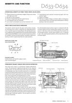
OPERATIONAL BENEFITS OF DIRECT DRIVE SERVO VALVES (DDV) Directly driven by a permanent magnet linear force motor with high force level No pilot oil flow required Pressure independent dynamic performance Low hysteresis and low threshold Low current consumption at and near hydraulic null Standardised spool position monitoring signal with low residual ripple Electric null adjust With loss of supply voltage, or broken cable, or emergency stop the spool returns to its spring centred position without passing a load move position. DIRECT DRIVE VALVE (DDV) OPERATION The position control loop for...
Abrir la página 3 del catálogo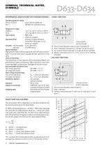
GENERAL TECHNICAL DATES, SYMBOLS PERFORMANCE SPECIFICATIONS FOR STANDARD MODELS Operating pressure range Ports P, A and B up to 350 bar (5000 psi) Port T see data for individual series Viscosity recommended allowed System filtration High pressure filter (without bypass, but with dirt alarm) mounted in the main flow and if possible directly upstream of the valve. Class of cleanliness The cleanliness of the hydraulic fluid particularly effects the performance (spool positioning, high resolution) and wear (metering edges, pressure gain, leakage) of the servo valve. Recommended cleanliness...
Abrir la página 4 del catálogo
GENERAL REQUIREMENTS FOR VALVE ELECTRONICS Supply 24 VDC, min. 19 VDC, max. 32 VDC Current consumption IAmax for D633 1.2 A for D634 2.2 A External fuse per valve for D633 1.6 A (slow) for D634 2.5 A (slow) All signal lines, also those of external transducers, shielded. Shielding connected radially to ⊥ (0 V), power supply side, and connected to the mating connector housing (EMC). EMC: Meets the requirements of emission: EN55011:1998+A1:1999 (limit class: B) and immunity: EN61000-6-2:1999 Minimum cross-section of all leads ≥ 0.75 mm2 (0.001 in2). Consider voltage losses between cabinet and...
Abrir la página 5 del catálogo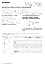
VALVE ELECTRONICS WITH SUPPLY VOLTAGE 24 VOLT AND 6+PE POLE CONNECTOR floating. Valves with current command input The spool stroke of the valve is proportional to lD = -lE. 100 % valve opening P ^ A and B ^ T is achieved at lD = +10 mA. At 0 mA command the spool is in centred positi- on. The input pins D and E are inverting. Either pin D or E is used according to the required operating direction. The other pin is connected to signal ground at cabinet side. Valves with voltage command input The spool stroke of the valve is proportional to (UD - UE). 100 % valve opening P ^ A and B ^ T is...
Abrir la página 6 del catálogo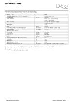
TECHNICAL DATA PERFORMANCE SPECIFICATIONS FOR STANDARD MODELS Model . . . Type Mounting pattern with or without leakage port Y 3) Port diameter Valve version 2) Spool actuation Pilot supply Mass Rated flow (±10%) at ΔpN= 35 bar per land Max. valve flow Operating pressure max. Ports P,A,B Port T ohne Y Port T mit Y Port Y Response time for 0 to 100% stroke, typical Threshold 1) Hysteresis 1) Null shift 1) with ΔT = 55 K Null leakage flow 1) max. (axis cut) 1) 2) 3) At operating pressure pp = 140 bar (2000psi), fluid viscosity of 32 mm2/s (0.05 in2/s) and fluid temperature of 40 °C (104° F)...
Abrir la página 7 del catálogo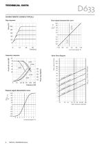
Time [ms] Command signal / % Frequency response Valve flow diagram Command signal / %
Abrir la página 8 del catálogo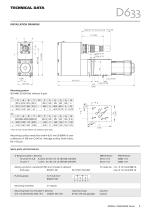
TECHNICAL DATA INSTALLATION DRAWING Mounting pattern ') Port X must not be drilled, not sealed at valve base. Mounting surface needs flat within 0,01 mm (0.0004 in) over a distance of 100 mm (3.94 in). Average surface finish value, Spare parts and Accessories O-Rings (included in delivery) for ports P,T,A,B 4 pieces ID 9,25 x 0 1,8 (ID 0.36 x 0 0.07) Mating connector, waterproof IP65 (not included in delivery) Flushing plates Mounting manifolds Mounting bolts (not included in delivery) required torque
Abrir la página 9 del catálogo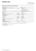
TECHNICAL DATA PERFORMANCE SPECIFICATIONS FOR STANDARD MODELS 1) At operating pressure pp = 140 bar (2000 psi), fluid viscosity of 32 mrnVs (0.05 in2/s) and fluid temperature of 40 °C (104° F) 3) Leakage port Y must be used
Abrir la página 10 del catálogo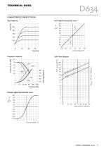
TECHNICAL DATA CHARACTERISTIC CURVES (TYPICAL) Step response Flow signal characteristic curve Command signal / % Frequency response Valve flow diagram Pressure signal characteristic curve Command signal / %
Abrir la página 11 del catálogo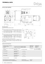
TECHNICAL DATA INSTALLATION DRAWING Mounting pattern Spare parts and Accessories O-Rings (included in delivery) Mating connector, waterproof IP65 (not included in delivery) Flushing plates Flushing plates Flushing plates Mounting manifolds Mounting bolts (not included in delivery) required torque
Abrir la página 12 del catálogo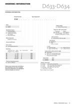
ORDERING INFORMATION ORDERING INFORMATION Type designation Signals for 100% spool stroke* Specification-Status Series specification E Preseries specification K explosion proof version upon request Z Special specification Command Output M ±10 VDC +4 to +20 mA X ±10 mA, floating +4 to +20 mA deadband compensation on request Valve connector Model designation assigned at the factory Seal material N V Factory identification NBR (Buna) FPM others on request with integrated electronics Y- port 0 closed with plug 3 open, with filter insert Rated flow QN[l/min] at ΔpN = 35 bar (QN[gpm] at ΔpN = 500...
Abrir la página 13 del catálogo
take a closer look. Moog solutions are only a click away. Visit our worldwide Web site for more information and the Moog facility nearest you. www.moog.com/industrial Moog is a registered trademark of Moog, Inc. All trademarks as indicated herein are the property of Moog Inc. and its subsidiaries. All rights reserved. ©2009 Moog Inc. D633 and D634 Servovalves GUT/100 04/2009 What moves your world
Abrir la página 14 del catálogoTodos los catálogos y folletos técnicos MOOG
-
 Servoválvulas Proporcionales
84 Páginas
-
 SINGLE AXIS DRIVE DS2020
16 Páginas
-
 MODEL 220 ROTARY SERVO ACTUATOR
7 Páginas
-
 Moog_Motion Systems_Catalogue_en
8 Páginas
-
 HYDRAULIC TEST ACTUATOR
14 Páginas
-
 MACHINE CONTROLLER MC 600 SERIES
28 Páginas
-
 TURRET TEST SYSTEMS
2 Páginas
-
 MOTION TECHNOLOGY
92 Páginas
-
 ELECTROHYDROSTATIC PUMP UNIT
52 Páginas
-
 High Performance Solenoids
4 Páginas
-
 FO242 Fiber optic rotary joint
2 Páginas
-
 FO215 Fiber optic rotary joint
2 Páginas
-
 High Current Management Unit (HCMU)
2 Páginas
-
 Actively Operated (CHE, RHE)
24 Páginas
-
 Spool Type (CKE, DMO)
12 Páginas
-
 Monopropellant Propulsion Module
2 Páginas
-
 Space Sector Brochure
7 Páginas
-
 Moog Machine Controller MC Series 600
44 Páginas
-
 Tire Coupled Simulation System
8 Páginas
-
 Data Acquisition Unit
2 Páginas
-
 Power and Voltage-Switching Unit
2 Páginas
-
 Motion Controllers
68 Páginas
-
 Hydraulic Service Manifold
8 Páginas
-
 Electrohydrostatic Pump Unit
28 Páginas
-
 TACTICAL FIBER OPTIC MODEMS
6 Páginas
-
 CONTROL LOADING SOLUTIONS
5 Páginas
-
 SERVODRIVE DS2110
16 Páginas
-
 A085 series
2 Páginas
-
 RADIAL PISTON PUMP
80 Páginas
-
 RKP-D RADIAL PISTON PUMP
31 Páginas
-
 Radial Piston Pump Size 250 cm^3
2 Páginas
-
 EFB & DCV/ACV Training
1 Páginas
-
 Moog Pitch Control Training
15 Páginas
-
 Rotor Monitoring Systems
2 Páginas
-
 Blade Sensing Systems
2 Páginas
-
 Wind Turbine Pitch Valve
2 Páginas
-
 Dynamic Energy Unit
2 Páginas
-
 Programmable Single-Axis Servo Drive
94 Páginas
-
 Programmable Multi-Axis Servo Drive System
139 Páginas
-
 HYDRAULIC SIMULATION TABLE
12 Páginas
-
 HYDRAULIC TEST ACTUATOR SINGLE-ENDED
12 Páginas
-
 RKP LIQUID FUEL METERING SYSTEM
2 Páginas
-
 HYDRAULIC PITCH PUMP
2 Páginas
-
 FLOW CONTROL SERVOVALVES J869 SERIES
8 Páginas
-
 FAILSAFE ELECTRO-MECHANICAL ACTUATOR
4 Páginas
-
 HYDRAULIC TEST ACTUATOR POLYMER BEARING
11 Páginas
-
 PITCH SERVO DRIVE FOR WIND TURBINES
12 Páginas
-
 DS2000XP High Performance Servodrives
12 Páginas
-
 MAXFORCE SIZE 6
19 Páginas
-
 MAXFORCE SIZE 5
18 Páginas
-
 MAXFORCE SIZE 4
18 Páginas
-
 MAXFORCE SIZE 3
18 Páginas
-
 ELECTRIC LINEAR SERVOACTUATORS
4 Páginas
-
 Axis Control Valve
2 Páginas
-
 MSD Servo Drive Compact
2 Páginas
-
 Gas and Steam Turbines
2 Páginas
-
 Falsafe Electro Mechanical Actuator
4 Páginas
-
 Ruggedized Motion Controller
2 Páginas
-
 Moog Industrial Capabilities Overview
16 Páginas


Catálogos archivados
-
 FASTACT T/F AC Servomotors
24 Páginas
-
 Fastact T/F Brushless Servo Motors
24 Páginas

