
Extractos del catálogo

Series A Junior Worm Gear Technical Up to - 12kW / 950 Nm Worm Gears CAJ-2.00GB1211
Abrir la página 1 del catálogo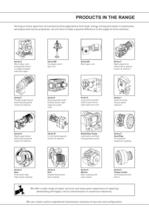
PRODUCTS IN THE RANGE Serving an entire spectrum of mechanical drive applications from food, energy, mining and metal; to automotive, aerospace and marine propulsion, we are here to make a positive difference to the supply of drive solutions. Series A Worm Gear units and geared motors in single & double reduction types Series BD Screwjack worm gear unit Series BS Worm gear unit Series C Right angle drive helical worm geared motors & reducers Series F Parallel angle helical bevel helical geared motors & reducers Series G Helical parallel shaft & bevel helical right angle drive gear units...
Abrir la página 2 del catálogo
ATEX Compliance Assured Total compliance with the ATEX Directive safeguarding the use of industrial equipment in potentially explosive atmospheres is assured for users of our geared products. Certification is available for standard gearboxes and geared motors with badging displaying the CE Mark and the Ex mark, name and location of the manufacturer, designation of series or type, serial number, year of manufacture, Ex symbol and equipment group/category. ATEX directive 94/9/EC (also known as ATEX 95 or ATEX 100A) and the CE Marking Directive are enforced in all EC member states. Compliance...
Abrir la página 3 del catálogo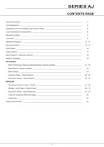
SERIES AJ CONTENTS PAGE General Description __________________________________________________________________ 3 Unit Designations ____________________________________________________________________ 4 Explanation and use of Ratings and Service Factors _________________________________________ 5 Load Classification by Applications ______________________________________________________ 6 Moments of Inertia ___________________________________________________________________ 7 Lubrication _________________________________________________________________________ 8 Selection Procedure...
Abrir la página 5 del catálogo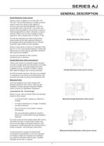
SERIES AJ GENERAL DESCRIPTION Single Reduction Units (worm) Series A Junior is offered in unit sizes 280, 410, 510, 610, 730 and 860 based on a single universal case for each size, giving a high degree of common parts and interchangeability. Units can be mounted in the under driven, over driven and vertical mounting positions and provide a choice of shaft arrangements for either motorised or reducer versions. Motors can be close coupled in frame sizes 63 to 132 in powers from 0.12 kW to 11 kW. All units are designed with hollow output bores, output shafts can be fitted allowing handing to...
Abrir la página 6 del catálogo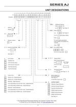
SERIES AJ UNIT DESIGNATIONS 1 2 3 4 5 6 7 8 9 10 11 12 13 14 15 16 17 18 19 20 * Example A 0 5 1 0 7 . 5 W R C - A - - - - - - - 20 1 - Series A Additional Features Paint, Lubricant, etc e.g. - Range A See Page 19 19 - Motor Required e.g. 2-4 - Size of Unit - A See Page 24 For R or G Types Without Motor 0 5 1 Enter - For slow speed applications where greater oil quantities are required 5 - Revision Version 0 F etc Enter D 6, 7, 8 - Nominal Overall Ratio e.g. 7 . 18 - No of Motor Poles 5 2 4 6 or 8 5 0 . For R or G Type enter - See Page 17 15, 16, 17 - 9 - Version Unit Geared Motor W -...
Abrir la página 7 del catálogo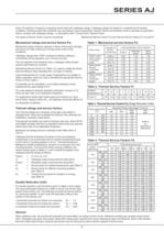
SERIES AJ Gear unit selection is made by comparing actual loads with catalogue ratings. Catalogue ratings are based on a standard set of loading conditions, whereas actual load conditions vary according to type of application. Service Factors are therefore used to calculate an equivalent load to compare with catalogue ratings. i.e. Equivalent Load = Actual Load x Service Factor Two types of Service Factor must be considered:- Mechanical Service Factor Fm and Thermal Service Factors Ft, Fp and Fd Mechanical ratings and service factors Fm Table 1. Mechanical service factors Fm Mechanical...
Abrir la página 8 del catálogo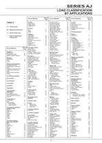
SERIES AJ LOAD CLASSIFICATION BY APPLICATIONS Driven Machine Table 5 U = Uniform load M = Moderate shock load H = Heavy shock load = Refer to Application Engineering Cranes main hoists bridge travel trolley travel type of load U Crusher ore H stone H sugar H Dredges cable reels M conveyors M cutter head drives H jig drives H manoeuvring winches M pumps M screen drive H stackers M utility winches M type of Dry dock cranes load main hoist auxiliary hoist boom, luffing Agitators rotating, swing or slew pure liquids U tracking, drive wheels liquids and solids M liquids-variable density M...
Abrir la página 9 del catálogo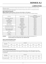
SERIES AJ LUBRICATION Series A Junior units are factory filled with a Polyglycol based synthetic lubricant. They are “Lubricated for Life” and require no routine maintenance in service. In the event of a major overhaul involving strip-down and re-assembly of the gear unit refer to Table 1 for a list of approved lubricants. Lubricant quantities are given in Tables 2 and 3. Table 1 Approved Lubricants Type G Polyglycol based synthetic lubricants with Anti-Wear or EP additives These lubricants are suitable for ambient temperatures of 0oC to 40oC; outside of this, please consult our Application...
Abrir la página 11 del catálogo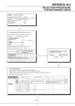
SERIES AJ SELECTION PROCEDURE FOR MOTORISED UNITS EXAMPLE APPLICATION DETAILS Absorbed power of driven machine = 0.38kW Output speed of gearbox or Input speed of machine = Application = Uniformly loaded belt conveyor Duration of service (hours per day) = 24hrs Mounting position = D Ambient temperature = 20oC Running time (%) = 100% 55rev/min 1 DETERMINE MECHANICAL SERVICE FACTOR (Fm) Refer to Load Classification by Application, table 5, page 7 Application = Uniformly loaded belt conveyor Conveyors-uniformly loaded or fed U apron U assembly U belt U bucket U chain U = Uniform load Refer to...
Abrir la página 12 del catálogo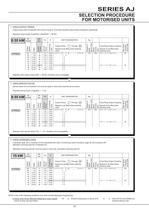
SERIES AJ SELECTION PROCEDURE FOR MOTORISED UNITS 4 CHECK OUTPUT TORQUE Output torque (M2) of selected unit must be equal or more than required output torque at gearbox outputshaft. Required output torque at gearbox outputshaft = 66 Nm 17 24 33 38 44 57 66 76 94 2.61 2.30 2.27 2.10 2.01 1.53 1.51 1.33 0.99 Column Entry 1 Through 20 Spaces to be filled when entering order Kg 2764 A 0 4 1 0 5 . 0 _ - _ _ . 5 5 A _ _M 4 19.4 80a 2764 7 . 5 2764 1 0 . 2758 1 3 . 2758 1 5 . 2748 2 0 . 2748 2 5 . 2742 3 0 . 2730 4 0 . Cone Ring Output Coupling Spaces to be filled when entering order Max Bore...
Abrir la página 13 del catálogoTodos los catálogos y folletos técnicos Radicon
-
 Product Brochure radicon
8 Páginas
-
 Metric
8 Páginas
-
 Series M Helical In-Line
116 Páginas
-
 BR-Series-AM.
72 Páginas
-
 adicon-SeriesX
32 Páginas
-
 Radicon Product Brochure metric
8 Páginas
-
 BR Series F
117 Páginas
-
 Radicon Series X Couplings
32 Páginas
-
 BR Series X Couplings
36 Páginas
-
 BR Cone Ring Couplings
16 Páginas
-
 Series J
73 Páginas
-
 Motor
Motor4 Páginas
-
 Series E Flyer
4 Páginas
-
 G series
4 Páginas
-
 BD
BD4 Páginas
-
 Benzlers Screw Jacks
69 Páginas
-
 Series J - Shaft Mounted Gearbox
15 Páginas
-
 Radicon Series ET
42 Páginas
-
 BR Series G
71 Páginas
-
 Series X Cone Ring Flexible Couplings
16 Páginas
-
 Geared Pump
15 Páginas
-
 Series P Planetary
4 Páginas
-
 M series
120 Páginas
-
 Sala Gears
74 Páginas
-
 Roloid Pump
17 Páginas
-
 Heavy Duty Worm Gear Series ER
15 Páginas
-
 Screw Jacks
58 Páginas
-
 Series AM Worm Gear
73 Páginas
-
 Series BS Worm Gear
60 Páginas
-
 Elflex Flexible Couplings
8 Páginas
-
 Series H industrial gearboxes
123 Páginas
-
 SERIE G
71 Páginas
-
 C series
120 Páginas
-
 Geared Motor Series K
90 Páginas
-
 F series
119 Páginas
-
 Elign Gear Couplings
17 Páginas

Catálogos archivados
-
 Worm Gears Series AH
13 Páginas


