VAMP 265M motor differential protection relay
1 /224Páginas
VAMP 265M motor differential protection relay
1 /224Páginas
Extractos del catálogo

Motor differential protection relay User manual
Abrir la página 1 del catálogo
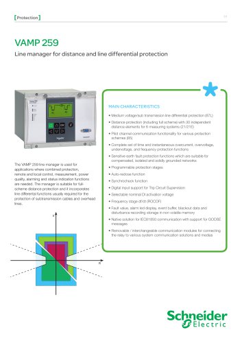
1 General 1. 1.1 Relay features General Chapter 1-3 of the publication contains general descriptions of the functions, of the differential protection relay as well as operation instructions. It also includes instructions for parameterization and configuration of the relay and instructions for changing settings. Chapter 4-16 of the publication includes detailed protection function descriptions as well as application examples and technical data sheets. 1.1. Relay features VAMP 265M differential protection relay is ideal for motor differential protection. The relay features the following protection...
Abrir la página 7 del catálogo
1.2 User interface 1.2. 1 General User interface The relay can be controlled in three ways: Locally with the push-buttons on the relay front panel Locally using a PC connected to the serial port on the front panel or on the rear panel of the relay (both cannot be used simultaneously) Via remote control over the remote control port on the relay rear panel. 1.3. Operating Safety HAZARD OF ELECTRIC SHOCK, EXPLOSION, OR ARC FLASH A live current transformer secondary circuit must not be opened without turning off the primary side of the transformer and short circuiting transformer secondary circuits...
Abrir la página 8 del catálogo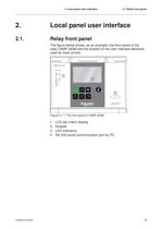
2 Local panel user interface 2.1 Relay front panel 2. Local panel user interface 2.1. Relay front panel The figure below shows, as an example, the front panel of the relay VAMP 265M and the location of the user interface elements used for local control. Figure 2.1-1. The front panel of VAMP 265M 1. 2. 3. 4. V265M/EN M/A004 LCD dot matrix display Keypad LED indicators RS 232 serial communication port for PC 9
Abrir la página 9 del catálogo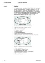
2.1 Relay front panel 2.1.1. 2 Local panel user interface Display The relay is provided with a back lighted 128x64 LCD dot matrix display. The display enables showing 21 characters in one row and eight rows at the same time. The display has two different purposes: one is to show the single line diagram of the relay with the object status, measurement values, identification etc. (Figure 2.1.1-1). The other purpose is to show the configuration and parameterization values of the relay (Figure 2.1.1-2). Figure 2.1.1-1 Sections of the LCD dot matrix display 1. 2. 3. 4. 5. 6. 7. Freely configurable...
Abrir la página 10 del catálogo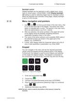
2 Local panel user interface 2.1 Relay front panel Backlight control Display backlight can be switched on with a digital input, virtual input or virtual output. LOCALPANEL CONF/Display backlight ctrl setting is used for selecting trigger input for backlight control. When the selected input activates (rising edge), display backlight is set on for 60 minutes. 2.1.2. Menu navigation and pointers 1. Use and to move up and down in the main menu, that is, on the left-hand side of the display. The active main menu option is indicated with a cursor. The options in the main menu items are abbreviations,...
Abrir la página 11 del catálogo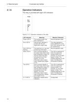
2.1 Relay front panel 2.1.4. 2 Local panel user interface Operation Indicators The relay is provided with eight LED indicators: Figure 2.1.4-1. Operation indicators of the relay LED indicator Power LED lit Error LED lit Com LED lit or flashing Alarm LED lit Trip LED lit A- C LED lit 12 Meaning The auxiliary power has been switched on Internal fault, operates in parallel with the self supervision output relay The serial bus is in use and transferring information One or several signals of the output relay matrix have been assigned to output LA and the output has been activated by one of the signals....
Abrir la página 12 del catálogo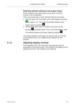
2 Local panel user interface 2.1 Relay front panel Resetting latched indicators and output relays All the indicators and output relays can be given a latching function in the configuration. There are several ways to reset latched indicators and relays: From the alarm list, move back to the initial display by pushing for approx. 3 s. Then reset the latched indicators and output relays by pushing . Acknowledge each event in the alarm list one by one by pushing equivalent times. Then, in the initial display, reset the latched indicators and output relays by pushing . The latched indicators and relays...
Abrir la página 13 del catálogo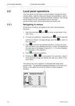
2.2 Local panel operations 2.2. 2 Local panel user interface Local panel operations The front panel can be used to control objects, change the local/ remote status, read the measured values, set parameters, and to configure relay functions. Some parameters, however, can only be set by means of a PC connected to one of the local communication ports. Some parameters are factory-set. 2.2.1. Navigating in menus All the menu functions are based on the main menu/submenu structure: 1. Use the arrow keys main menu. and to move up and down in the 2. To move to a submenu, repeatedly push until the required...
Abrir la página 14 del catálogo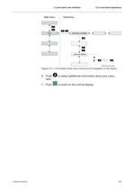
2 Local panel user interface 2.2 Local panel operations Figure 2.2.1-2 Principles of the menu structure and navigation in the menus 6. Push item. 7. Push V265M/EN M/A004 to obtain additional information about any menu to revert to the normal display. 15
Abrir la página 15 del catálogo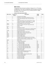
2.2 Local panel operations 2 Local panel user interface Main menu The general menu structure is shown in Figure 2.2.1-2. The menu is dependent on the user‘s configuration and the options according the order code. For example only the enabled protection stages will appear in the menu. A list of the local main menu Main menu Number of menus 1 5 1 Meas Imax Month 9 21 Evnt DR Runh 2 2 2 TIMR DI DO ExtAI ExDI ExDO Prot 6 5 4 3 3 3 8 Mstat N> ΔI> ΔI>> I> I>> I‘> I‘>> Ist> I< I2> I2>> 1 4 7 5 5 3 5 3 3 3 3 3 I‘2> T> Io> Io>> Io>>> 16 13 3 3 5 3 3 Description Interactive mimic display Double size measurements...
Abrir la página 16 del catálogo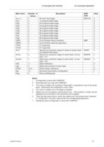
2 Local panel user interface Main menu Io>>>> Prg1 Prg2 Prg3 Prg4 Prg5 Prg6 Prg7 Prg8 CBFP CBWE CTSV CT‘SV ArcI> Number of menus 3 3 3 3 3 3 3 3 3 3 4 1 1 4 ArcIo> 3 ArcIo2> 3 OBJ Lgic CONF Bus Diag 11 2 10+2 13 6 2.2 Local panel operations Description 4th earth fault stage 1st programmable stage 2nd programmable stage 3rd programmable stage 4th programmable stage 5th programmable stage 6th programmable stage 7th programmable stage 8th programmable stage Circuit breaker failure protection Circuit breaker wearing supervision CT supervisor CT‘ supervisor Optional arc protection stage for phase-to-phase...
Abrir la página 17 del catálogoTodos los catálogos y folletos técnicos Vamp
 VAMP 57
16 Páginas
 VB 40
VB 408 Páginas
 VAMP 50
16 Páginas
 VAMP 230
16 Páginas
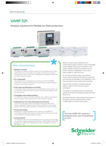 VAMP 321
12 Páginas
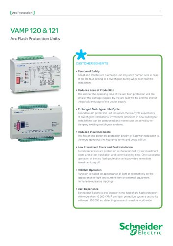
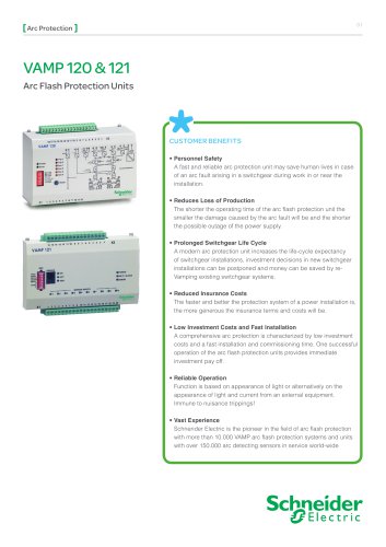 VAMP 120 & 121
8 Páginas
 vamp 265
2 Páginas
 VAMP 11V
16 Páginas
 VAMP 1 1 F
16 Páginas
 VAMP 50 series
20 Páginas
 VAMP 96 and VAMP 260
12 Páginas
 VAMP 259
12 Páginas
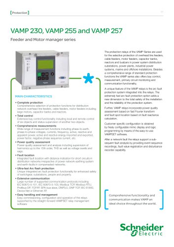 VAMP 230, VAMP 255 and VAMP 257
16 Páginas
 VAMP 125
1 Página
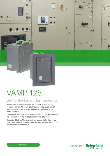 VAMP 125 Unit for flexible
12 Páginas
 VAMP 11V
16 Páginas
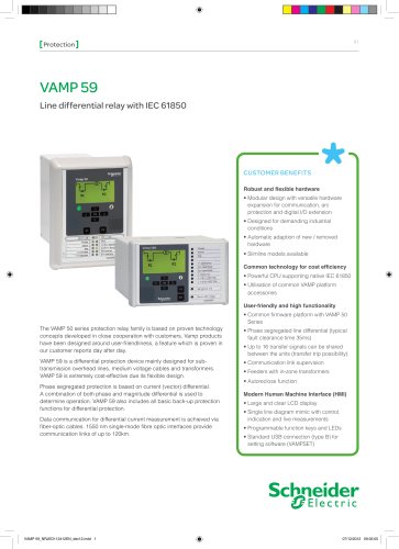 VAMP 59
12 Páginas
 VAMP 55
190 Páginas
 VAMP 120
8 Páginas
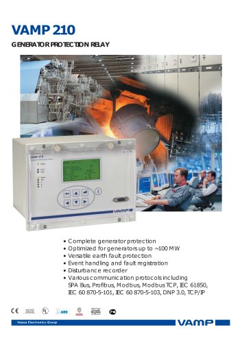 VAMP 210
2 Páginas
 VAMP 135
8 Páginas
Catálogos archivados
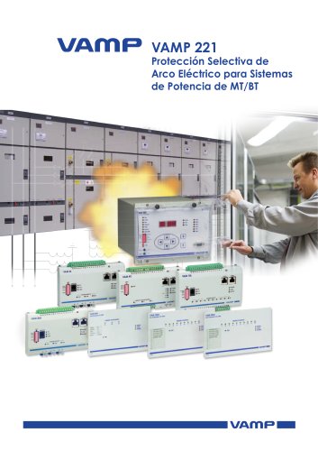 VAMP 221
16 Páginas
 VAMP 221_2013
16 Páginas
 VAMP 96
16 Páginas
 ARC Protection
20 Páginas
 Customer
28 Páginas
 Vamp Arc Protection Series
16 Páginas
 Vamp Feeder/Motor Manager
16 Páginas
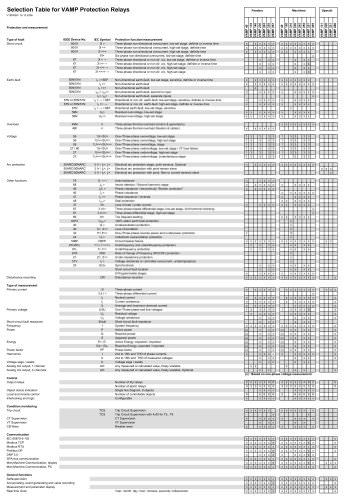 Selection table
1 Página
 Vamp Protection Relays
16 Páginas
- E/S digital
- Módulo E/S
- Software Windows
- Módulo E/S digital
- Relé de protección
- Módulo E/S de bus de campo
- Cable óptico
- Software de programación
- Cable óptico de datos
- Convertidor en serie
- Relé de protección de corriente
- Módulo de interfaz
- Relé de protección digital
- Relé de protección de tensión
- Software de autómata programable
- Relé de protección para motor eléctrico
- Relé de protección para montaje en panel
- Relé de protección programable
- Convertidor de fibras ópticas
- Relé de protección de fuga a tierra